Packaging and First Contact
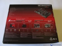
The motherboard comes with the Fatal1ty logo (the image of the famous computer gamer) on the front of the box, while in the back we can obtain a detailed description of most of the features of the motherboard itself. Inside, however, we find a short story about the origins of the Fatal1ty brand with more technical descriptions. Finally, we can see the motherboard through a transparent window.
Now we proceed with unboxing: there is a quick installation guide, two manuals, CD media, the the I/O rear panel shield, two EIDE cables, 4 SATA cables, an audio cable.
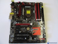
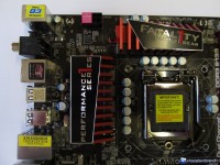
Once unwrapped the box, we can see the motherboard in its entirety, and its size, which correspond to the classic ATX standard (30.5 cm x 24.4 cm). Analyzing the socket area (LGA 1155), we can immediately see the CCO system that allows us to also use the dissipation systems for the obsolete 775 LGA socket, thanks to the tilted axis holes in respect to those for the LGA 1155 socket. Around the socket the capacitors and the MOSFET dissipation system, characterized by Fatal1ty logos, stand out. The power system has 8 plus 2 phases, the latter dedicated to memory controller and System Agent power; on the socket's right we see the four dedicated slots for RAM, pointing out that this motherboard supports up to 32GB of memory with a maximum frequency of 2133 MHz in overclock with full support for XMP (Extreme Memory Profile).
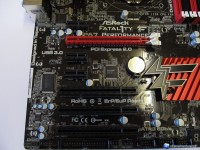
Going to the bottom of the PCB (below the socket), we see the PCIe 2.0 x16 slot, the only one on which we can install a video card; in addition to these there are three PCIe 2.0 x1 slots and three simple PCI slots. On the perimeter of the board, under the last PCIe slot, instead, we find the floppy connector, the COM port connector and 6 additional USB 2.0 ports. The only 2 USB 3.0 ports, supported by the EtronTech EJ168A controller, are on the rear I/O panel.
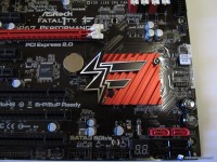
On the bottom left side we find, instead, the beautiful heatsink dedicated to the P67 chipset with the Fatal1ty logo clearly visible; in addition to this there is the "Dr. Debug" LED display that allows overclockers to quickly understand what is happening to their system at boot. We also notice the the two dedicated buttons for power on and system reset, also very useful for overclockers; a little bit upside we can see 2 red colored 6Gb/s SATA ports, accompanied by additional 4 black 3 Gb/s SATA ports.
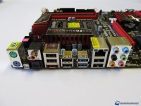
Let's give a last look at the I/O back panel, which is very complete, with 1 PS/2 port for mouse or keyboard, SPDIF optical output, SPDIF coaxial port, 5 USB 2.0 ports, a Fatal1ty mouse port, 1 eSATA connector, 2 USB 3.0 ports, 2 Ethernet ports, 1 Clear CMOS switch and finally the small 6 jacks audio panel.
